
We continue to improve our STM32CubeMx course and today we’ll speak about the combined usage of SPI and DMA peripherals. Of course, we’ll also create an example for STM32 microcontrollers. To make our task more difficult I’ve decided to use four SPI modules and respectively four different DMA channels. So, let’s begin immediately! 🙂
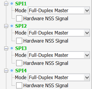
Firstly, we should create the new project in the STM32CubeMx application. Don’t forget to choose the proper MCU when creating the project (as for me, I’ll use STM32F429). Secondly, we should enable all necessary SPI peripherals:
As a result STM32CubeMx marked 12 GPIOs which are used for SPI communication:
- SPI1_SCK
- SPI1_MOSI
- SPI1_MISO
- SPI2_SCK
- SPI2_MOSI
- SPI2_MISO
- SPI3_SCK
- SPI3_MOSI
- SPI3_MISO
- SPI4_SCK
- SPI4_MOSI
- SPI4_MISO
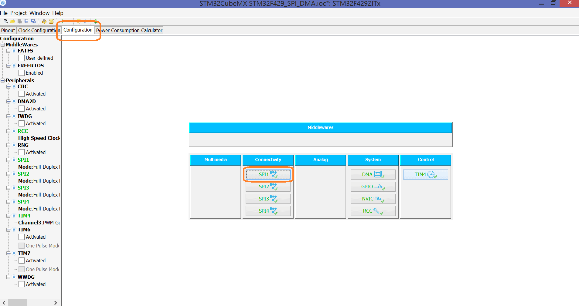
Let’s open the configuration tab. To activate the STM32 DMA channels for SPI modules we should add some extra configuration. So, click on the SPI1 button.
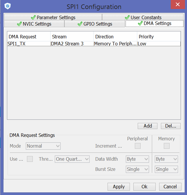
In this window we are interested in the “DMA Settings” tab. To add the DMA channel to SPI1 we should click on the “Add” button and choose the necessary DMA channel. In this example we’ll use only SPI1_TX DMA request:
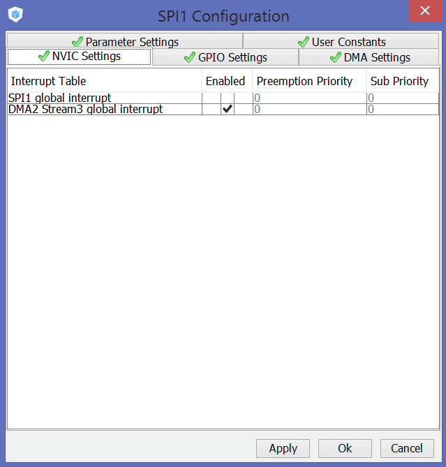
Moreover, let’s enable the DMA interrupt. It will occure, when the transmission is completed. Thus, we’ll be able to start the new data exchange:
Now, we should repeat all these steps for other SPI peripherals (SPI2, SPI3, SPI4). There are no differences between the configurations of different modules, so, we won’t stop on this point. After that, the configuration is fully completed, so, we can begin the programming process 🙂
Let’s look at some generated functions using the SPI1 module as an example. First of all, the initialization function is called:
void MX_SPI1_Init(void)
{
	hspi1.Instance = SPI1;
	hspi1.Init.Mode = SPI_MODE_MASTER;
	hspi1.Init.Direction = SPI_DIRECTION_2LINES;
	hspi1.Init.DataSize = SPI_DATASIZE_8BIT;
	hspi1.Init.CLKPolarity = SPI_POLARITY_LOW;
	hspi1.Init.CLKPhase = SPI_PHASE_1EDGE;
	hspi1.Init.NSS = SPI_NSS_SOFT;
	hspi1.Init.BaudRatePrescaler = SPI_BAUDRATEPRESCALER_8;
	hspi1.Init.FirstBit = SPI_FIRSTBIT_MSB;
	hspi1.Init.TIMode = SPI_TIMODE_DISABLED;
	hspi1.Init.CRCCalculation = SPI_CRCCALCULATION_DISABLED;
	HAL_SPI_Init(&hspi1);
}
The DMA initialization is held in the HAL_SPI_MspInit() function:
hdma_spi1_tx.Instance = DMA2_Stream3;
hdma_spi1_tx.Init.Channel = DMA_CHANNEL_3;
hdma_spi1_tx.Init.Direction = DMA_MEMORY_TO_PERIPH;
hdma_spi1_tx.Init.PeriphInc = DMA_PINC_DISABLE;
hdma_spi1_tx.Init.MemInc = DMA_MINC_ENABLE;
hdma_spi1_tx.Init.PeriphDataAlignment = DMA_PDATAALIGN_BYTE;
hdma_spi1_tx.Init.MemDataAlignment = DMA_MDATAALIGN_BYTE;
hdma_spi1_tx.Init.Mode = DMA_NORMAL;
hdma_spi1_tx.Init.Priority = DMA_PRIORITY_VERY_HIGH;
hdma_spi1_tx.Init.FIFOMode = DMA_FIFOMODE_DISABLE;
HAL_DMA_Init(&hdma_spi1_tx);

__HAL_LINKDMA(hspi,hdmatx,hdma_spi1_tx);
All interrupts are located in the file stm32f4xx_it.c (if you use another microcontroller this file could have another name, for example, stm32f1xx_it.c. As we activated four interrupt requests, let’s define four flags which will indicate the transmission status for all SPIs:
uint8_t completed1 = 1;
uint8_t completed2 = 1;
uint8_t completed3 = 1;
uint8_t completed4 = 1;
You should also declare these variables in all of the files where they are used:
extern uint8_t completed1;
extern uint8_t completed2;
extern uint8_t completed3;
extern uint8_t completed4;
If the completed1 flag is set to 1, the data exchange via SPI1 is finished. If it is set to 0, the SPI1 peripheral is busy. Thus, we should reset the flag when starting the transmission and set it when the transmission is completed. Let’s edit the interrupt handlers:
/**
* @brief This function handles DMA2 Stream3 global interrupt.
*/
void DMA2_Stream3_IRQHandler(void)
{
	/* USER CODE BEGIN DMA2_Stream3_IRQn 0 */
	completed1 = 1;
	/* USER CODE END DMA2_Stream3_IRQn 0 */

	HAL_DMA_IRQHandler(&hdma_spi1_tx);

	/* USER CODE BEGIN DMA2_Stream3_IRQn 1 */
	/* USER CODE END DMA2_Stream3_IRQn 1 */
}


/**
* @brief This function handles DMA2 Stream1 global interrupt.
*/
void DMA2_Stream1_IRQHandler(void)
{
	/* USER CODE BEGIN DMA2_Stream1_IRQn 0 */
	completed4 = 1;
	/* USER CODE END DMA2_Stream1_IRQn 0 */

	HAL_DMA_IRQHandler(&hdma_spi4_tx);

	/* USER CODE BEGIN DMA2_Stream1_IRQn 1 */

	/* USER CODE END DMA2_Stream1_IRQn 1 */
}


/**
* @brief This function handles DMA1 Stream4 global interrupt.
*/
void DMA1_Stream4_IRQHandler(void)
{
	/* USER CODE BEGIN DMA1_Stream4_IRQn 0 */
	completed2 = 1;
	/* USER CODE END DMA1_Stream4_IRQn 0 */

	HAL_DMA_IRQHandler(&hdma_spi2_tx);

	/* USER CODE BEGIN DMA1_Stream4_IRQn 1 */

	/* USER CODE END DMA1_Stream4_IRQn 1 */
}


/**
* @brief This function handles DMA1 Stream5 global interrupt.
*/
void DMA1_Stream5_IRQHandler(void)
{
	/* USER CODE BEGIN DMA1_Stream5_IRQn 0 */
	completed3 = 1;
	/* USER CODE END DMA1_Stream5_IRQn 0 */

	HAL_DMA_IRQHandler(&hdma_spi3_tx);

	/* USER CODE BEGIN DMA1_Stream5_IRQn 1 */

	/* USER CODE END DMA1_Stream5_IRQn 1 */
}
Moreover, we should declare the data array and fill it with the test data:
uint8_t testDataToSend[128];

for (uint8_t i = 0; i < 128; i++)
{
	testDataToSend[i] = i + 1;
}
And the final step is calling the HAL_SPI_Transmit_DMA() function in order to send the data. Don’t forget to reset the status flag:
completed1 = 0;
HAL_SPI_Transmit_DMA(&hspi1, testDataToSend, 128);
Similarly, add the following code for SPI2 data exchange:
completed2 = 0;
HAL_SPI_Transmit_DMA(&hspi2, testDataToSend, 128);
After that we should wait while the status flag is reset, before we can start the new transmission.
So that's all for today, don’t miss the new posts on MicroTechnics! 🙂

 usage with STM32CubeMx.")
.")

hello i do exactly these things but when i call the hal_spi_transmit_dma() the debugger jumps to hardfault handler. whatever i did, i couldnt find what i am doing wrong... any ideas?
Hello!
Maybe interrupt handler is not defined? Can you look with the debugger which instruction causes hardfault?
i found the mistake. i am running out of memory when i init an array but somehow it doesnt crash until i try to dma it...
Hi How to set the DMA to send data from GPIO
How do you read the data received from the SPi ?
You can use HAL_SPI_Receive_DMA() function to get data from SPI.
completedX should be volatile don't you think?
Anyone got this working ?
When I try this, I get :
Error[Pe020]: identifier "Wait_For_Spi_Dac" is undefined.
I declared the Variable in main.c:
volatile int Wait_For_Spi_Dac; (tried uint16_t, float, and without volatile)
And added my change to the "Wait" flag in the stm32l4xx_it.c file interrupt routine:
void DMA1_Channel5_IRQHandler(void)
{
Wait_For_Spi_Dac = 0;//Clear wait flag
HAL_DMA_IRQHandler(&hdma_spi2_tx);
}
It seems like I cannot access any variables (declared in main.c) in the stm32l4xx_it.c file.
I am using IAR Embedded workbench and STM32CubeMX.
Do I somehow need to "include" something ?
Solved, in the interrupt.c file one must add the "extern" statement for the used variable, like this:
extern uint16_t Wait_Flag;
Is there a way to have the DMA continuously read a byte a SPI slave and save it to memory? I'd like the CPU to be able to read the latest value at any time!