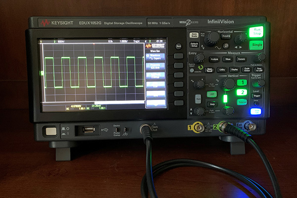
Hi to all! In one of previous posts I promised to tell about the clock configuration in the STM32CubeMx. So this article is devoted to the RCC and the clock frequencies. We’ll also consider some examples today, so we’ll take the project from the post about the timer configuration as a basis. Let’s open this project and proceed to the “Clock configuration” tab:
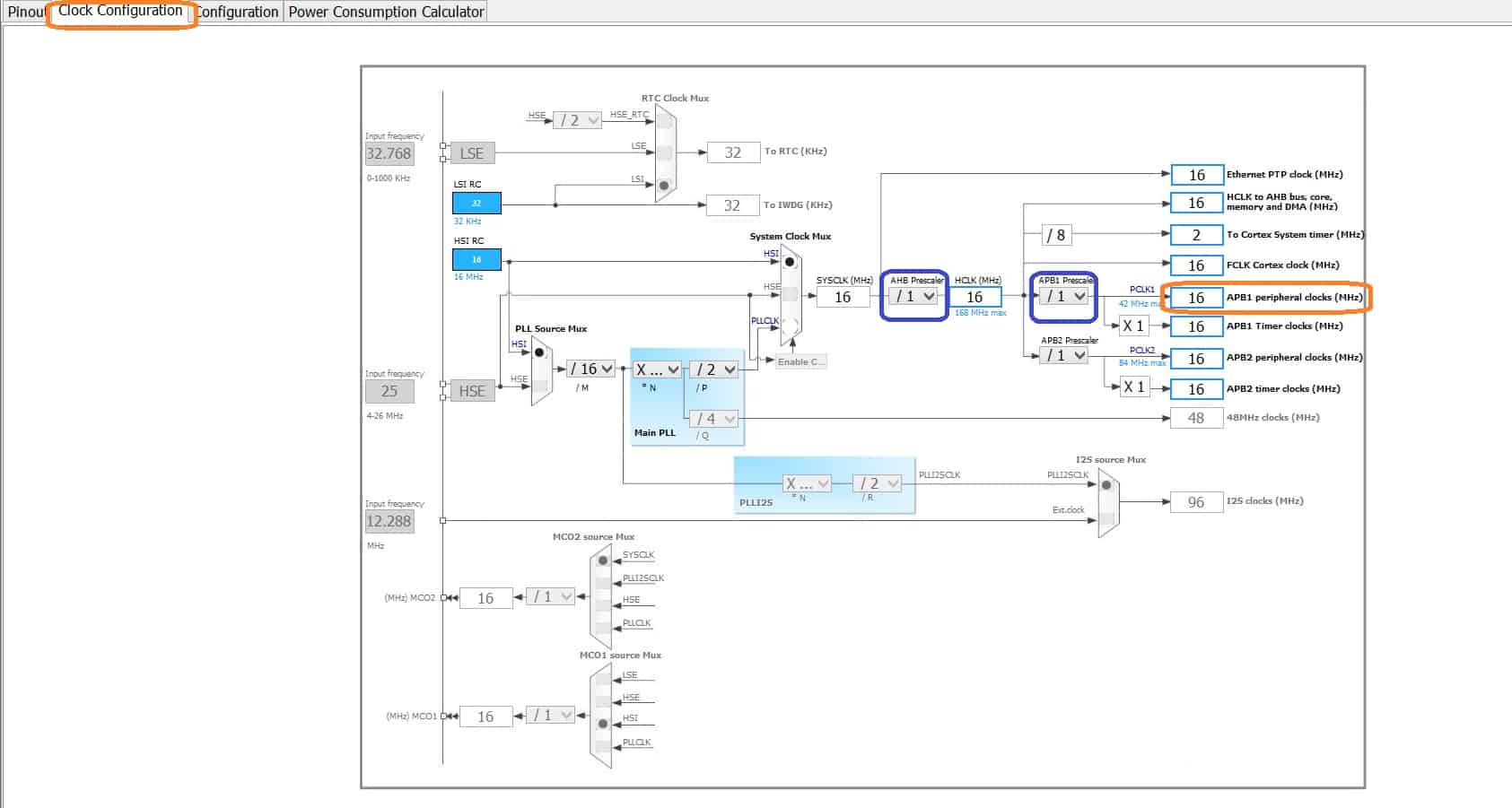
As you see the input clock signal is taken from the internal high-frequency oscillator (16 MHz). Before the clock signal comes to the APB1 bus, it passes through the two clock dividers, which are marked with blue color in the screenshot. So, the APB1 frequency is set to 16 MHz (16 / 1 / 1). When we created the project for timers, we’ve used this value for the period calculating.
Let’s increase the value of APB1 Prescaler and regenerate the project:
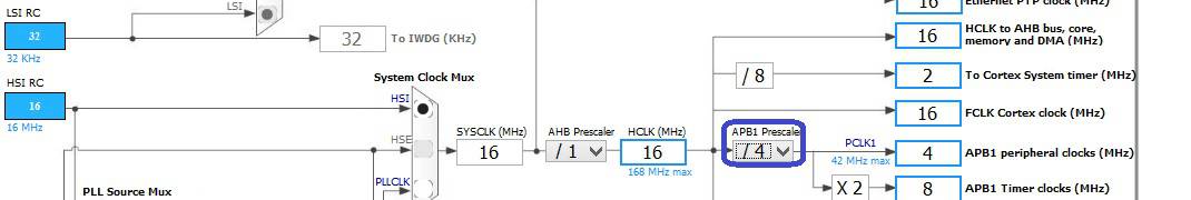
Now the TIM3 timer frequency is 8 MHz. Let’s look at the RCC configuration function in the main.c file:
void SystemClock_Config(void)
{
	RCC_OscInitTypeDef RCC_OscInitStruct;
	RCC_ClkInitTypeDef RCC_ClkInitStruct;

	__PWR_CLK_ENABLE();

	__HAL_PWR_VOLTAGESCALING_CONFIG(PWR_REGULATOR_VOLTAGE_SCALE2);

	RCC_OscInitStruct.OscillatorType = RCC_OSCILLATORTYPE_HSI;
	RCC_OscInitStruct.HSIState = RCC_HSI_ON;
	RCC_OscInitStruct.HSICalibrationValue = 6;
	RCC_OscInitStruct.PLL.PLLState = RCC_PLL_NONE;
	HAL_RCC_OscConfig(&RCC_OscInitStruct);

	RCC_ClkInitStruct.ClockType = RCC_CLOCKTYPE_PCLK1;
	RCC_ClkInitStruct.SYSCLKSource = RCC_SYSCLKSOURCE_HSI;
	RCC_ClkInitStruct.AHBCLKDivider = RCC_SYSCLK_DIV1;
	RCC_ClkInitStruct.APB1CLKDivider = RCC_HCLK_DIV4;
	RCC_ClkInitStruct.APB2CLKDivider = RCC_HCLK_DIV1;
	HAL_RCC_ClockConfig(&RCC_ClkInitStruct, FLASH_LATENCY_0);
}
As you see the prescaler value has been changed:
RCC_ClkInitStruct.APB1CLKDivider = RCC_HCLK_DIV2;
Please, note that our own code in the timer interrupt handler wasn’t deleted by the STM32CubeMx after the project had been regenerated. The reason is that we put it into the special code section:
/* USER CODE BEGIN 1 */

/* USER CODE END 1 */
Now, let’s compile the project and program the MCU. After that, we’ll see that the led blinking frequency is half as much as the previous frequency. The clock frequency has been reduced due to our changes in the project. As you remember we’ve increased the APB1 prescaler value.
So, this point is clear, now we will configure the external high-frequency oscillator (HSE). First of all, it should be enabled at the “Pinout” tab. Let’s return to the “Clock Configuration” tab and set the TIM3 frequency to the value of 48 MHz. The clock dividers’ proper values are shown in the following picture:
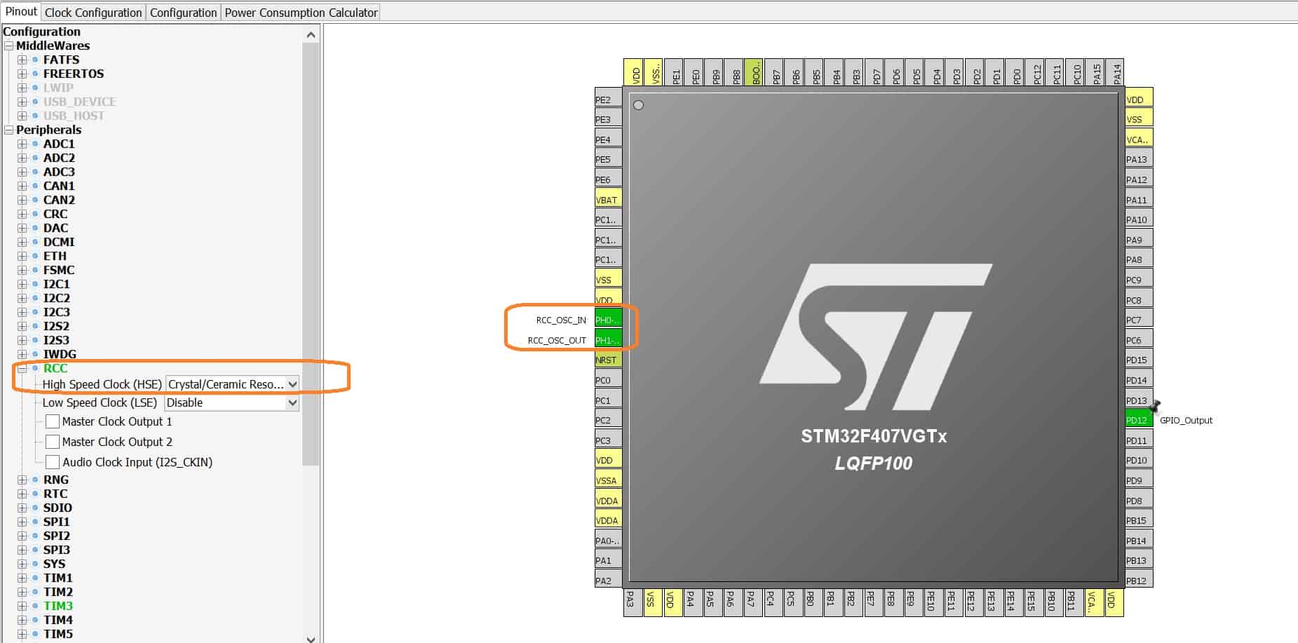
As the 8 MHz oscillator is mounted on the development board, this value should be set in the “Input frequency” box. After programming the microcontroller, we’ll see that the led is blinking three times “faster”. The reason is the increased timer frequency (16 MHz -> 48 MHz).
To conclude this post, I would say that the clock configuration in the STM32CubeMx framework is a very clear process, because it has a very user friendly interface 🙂 Thank you for your attention!


hello aveal,
thanks a lot for your tutorial.
i followed one of your tutorial on usb mass storage.and got usb mass storage working.but i have confusion for clock configuration here.
i implemented usb mass storage using external clock,but i have implemented my full application on internal clock,my spi is getting clock form internal source, so now i want to switch whole project on external source,so what should i do now?
thanks
Hello!
You can just switch settings to external source. And after that you can correct some frequencies (APB1, APB2 etc) with new divider values (if needed).
Hello gays, when I configurate the RCC clock, there are three options as "Bypass clock source", "Crystal/Ceramic Resonator" & "disable".
So the question is what is the different between “disable” and “Bypass Clock source”? Which one I need to choose for using the internal Clock(HSI or LSI)?
(Of cause "Crystal..." is mean use the external crystal)
Thanks!
Hello!
If you want to use internal clock you should choose "Disable".
"Crystal/Ceramic Resonator" is for external HSE crystal.
And “Bypass clock source” is for external source signal. For example from STM32F4 reference manual:
"In this mode, an external clock source must be provided. You select this mode by setting the HSEBYP and HSEON bits in the RCC clock control register (RCC_CR). The external clock signal (square, sinus or triangle) with ~50% duty cycle has to drive the OSC_IN pin while the OSC_OUT pin should be left HI-Z."
What is this difference in timer configuration in CubeMx if the clock is Disable / internal, if i mark the clock as disable does it again take the internal clock APB2 clock for the STM32G431TRB series.