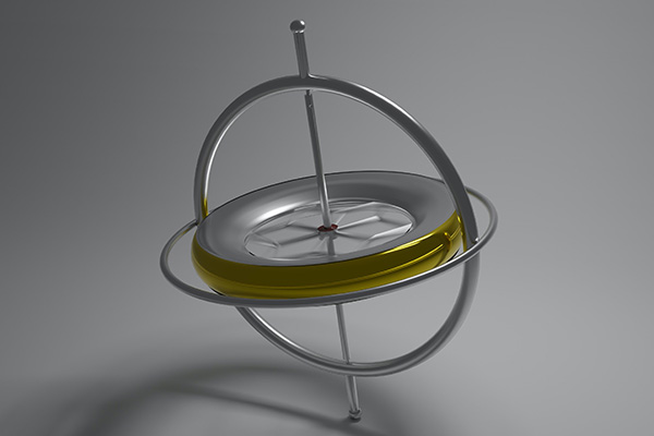
Today I would like to talk with you about the L3GD20 digital gyroscope. We will discuss the main features of this sensor and create an example project for STM32 microcontroller.
L3GD20 – is a small chip, produced by the STMicroelectronics. It can measure the three-axis angular rate and provide it through a digital interface – I2C or SPI. This sensor is mounted on the STM32F3Discovery board, so I’ll use it for this project. L3GD20 is connected to the MCU via SPI interface:
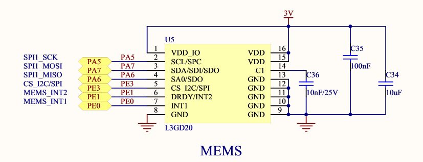
The serial interface interacts with the outside world through 4 wires: CS, SPC, SDI and SDO. Here is the data exchange protocol:
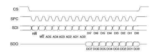
Chip Select (CS) signal goes low at the start of the transmission and goes high at the end. When the CS is high the master (MCU) should provide the Serial Port Clock signal (SPC). This is quite clear 🙂 Let’s proceed to the data format.
The first transmitted bit is R/W bit:
- If it is set to 1, we will read the measured data from the sensor
- If we’d like to write some data to the L3GD20, we should reset this bit.
The second bit is MS. When it is set to 1 the address will be auto-incremented in multiple read/write commands. For example, we’d like to transmit the write command consisting of the following parts:
- The address value which equals 0x01
- MS bit is set
- Five data bytes
As a result of transmitting this command, the data will be written to the registers with addresses 0x01/0x02/0x03/0x04/0x05.
The next six bits in the data frame are the address bits of the indexed register. And the following bytes are the data that will be written/read to/from the device. So, the protocol is clear, let’s proceed to the creating of the project! Please note, that I’ll use Standard Peripheral Library (SPL) and CMSIS in this project. Thus, all the library files should be added to the project.
L3GD20 registers are shown in the following table:
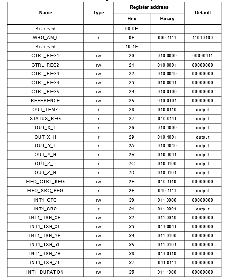
In order to turn on the sensor we should write the byte 0x0F to the register CTRL_REG1. After that, let’s read the data from any register and check it's value. For instance, we can take WHO_AM_I register. It's value should be equal 0xD4.
Let’s create the new project and add library files:
/**************************************************************************************************/
#include "stm32f30x_gpio.h"
#include "stm32f30x_rcc.h"
#include "stm32f30x_spi.h"
#include "stm32f30x.h"


/**************************************************************************************************/
Then let’s declare all variables:
/**************************************************************************************************/
#define DUMMY                                                    0x00
#define TIMEOUT_TIME                                             0x1000

SPI_InitTypeDef spi;
GPIO_InitTypeDef gpio;
uint8_t sendData;
uint8_t receiveData[8];;
uint16_t timeout;
uint8_t tempByte;


/**************************************************************************************************/
The next step is to create the initialization function:
/**************************************************************************************************/
void initAll()
{
	// RCC settings
	RCC_AHBPeriphClockCmd(RCC_AHBPeriph_GPIOA, ENABLE);
	RCC_AHBPeriphClockCmd(RCC_AHBPeriph_GPIOE, ENABLE);
	RCC_APB2PeriphClockCmd(RCC_APB2Periph_SPI1, ENABLE);

	// PA5, PA6 and PA7 are SPI pins
	GPIO_PinAFConfig(GPIOA, GPIO_PinSource5, GPIO_AF_5);
	GPIO_PinAFConfig(GPIOA, GPIO_PinSource6, GPIO_AF_5);
	GPIO_PinAFConfig(GPIOA, GPIO_PinSource7, GPIO_AF_5);

	gpio.GPIO_Mode = GPIO_Mode_AF;
	gpio.GPIO_Pin = GPIO_Pin_5 | GPIO_Pin_6 | GPIO_Pin_7;
	gpio.GPIO_OType = GPIO_OType_PP;
	gpio.GPIO_Speed = GPIO_Speed_50MHz;
	GPIO_Init(GPIOA, &gpio);

	// Chip Select pin
	gpio.GPIO_Mode = GPIO_Mode_OUT;
	gpio.GPIO_Pin = GPIO_Pin_3;
	gpio.GPIO_OType = GPIO_OType_PP;
	gpio.GPIO_Speed = GPIO_Speed_50MHz;
	GPIO_Init(GPIOE, &gpio);

	// Configure and enable the SPI peripheral
	spi.SPI_Direction = SPI_Direction_2Lines_FullDuplex;
	spi.SPI_DataSize = SPI_DataSize_8b;
	spi.SPI_CPOL = SPI_CPOL_High;
	spi.SPI_CPHA = SPI_CPHA_2Edge;
	spi.SPI_NSS = SPI_NSS_Soft;
	spi.SPI_BaudRatePrescaler = SPI_BaudRatePrescaler_8;
	spi.SPI_FirstBit = SPI_FirstBit_MSB;
	spi.SPI_CRCPolynomial = 7;
	spi.SPI_Mode = SPI_Mode_Master;
	SPI_Init(SPI1, &spi);

	SPI_Cmd(SPI1, ENABLE);

	SPI_RxFIFOThresholdConfig(SPI1, SPI_RxFIFOThreshold_QF);

	SPI_DataSizeConfig(SPI1, ENABLE);
}


/**************************************************************************************************/
Now, we need some functions in order to write and read gyroscope data:
/**************************************************************************************************/
uint8_t sendByte(uint8_t byteToSend)
{
	timeout = TIMEOUT_TIME;
	while ((SPI_I2S_GetFlagStatus(SPI1, SPI_I2S_FLAG_TXE) == RESET) & (timeout != 0))
	{
		timeout--;
	}

	SPI_SendData8(SPI1, byteToSend);

	timeout = TIMEOUT_TIME;
	while ((SPI_I2S_GetFlagStatus(SPI1, SPI_I2S_FLAG_RXNE) == RESET) & (timeout != 0))
	{
		timeout--;
	}

	return (uint8_t)SPI_ReceiveData8(SPI1);
}


/**************************************************************************************************/
void writeData(uint8_t address, uint8_t dataToWrite)
{
	GPIO_ResetBits(GPIOE, GPIO_Pin_3);
	sendByte(address);
	sendByte(dataToWrite);
	GPIO_SetBits(GPIOE, GPIO_Pin_3);
}


/**************************************************************************************************/
uint8_t readData(uint8_t address)
{
	GPIO_ResetBits(GPIOE, GPIO_Pin_3);
	sendByte(address);
	tempByte = sendByte(DUMMY);
	GPIO_SetBits(GPIOE, GPIO_Pin_3);
	return tempByte;
}


/**************************************************************************************************/
The first function named sendByte() will be used both in the write and read functions. Please note the using of the extra timeout in the while() cycle. It is done in order to prevent the program freezing.
In the writeData() function we transmit the address byte (including bits R/W and MS) and the data byte. Don’t forget to set Chip Select low before transmission and to set it high after it.
The readData() function is a lot like the writeData() function, but there is one important difference. It’s not enough to send the address byte, the MCU should also provide the clock signal in order to read the data from the sensor. To do this we should send a dummy byte (0x00) to the sensor.
Now, it’s time to add the main() function to our project:
/**************************************************************************************************/
int main()
{
	initAll();
	writeData(0x20, 0x0F);

	while(1)
	{
		receiveData[0] = readData(0x8F);
	}
}


/**************************************************************************************************/
Firstly, we initialize the gyroscope and, secondly, read the data from it in the while() cycle. Let’s compile the project and program the MCU. After that, we can start the debug session and check the read data:
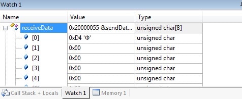
As you see the value is correct! We’ll continue testing the L3GD20 gyroscope in the future posts, so subscribe to the MicroTechnics and visit our site again! 🙂

 usage with STM32CubeMx.")
.")

I do not understand where the address bit of L3GD20 is 7 bits but in the SPI frame the address is only 6 bits