My aim for today’s post is to show an example of Virtual COM Port USB mode. Some time ago we worked with the USB Mass Storage mode - please don't miss this article 🙂
In previous posts devoted to the STM32CubeMx I've used the STM32F4Discovery board, so today I'll use it again 🙂 It's very suitable for our aims, because it can be connected to the PC via micro-USB connector mounted on the board. Thus, let's launch the STM32CubeMx and create a new project. This process is quite clear, because we've done it a lot of times in previous posts.
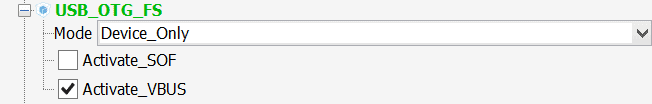
In this project we'll realize the Virtual COM Port driver for our microcontroller and try to send a small amount of data via USB. And, first of all, we should enable the USB peripheral. This can be done by setting the mode of the USB_OTG_FS module at the “Pinout” tab.
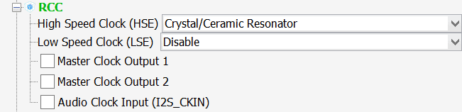
Furthermore, let’s enable the external 8 MHz crystal oscillator:
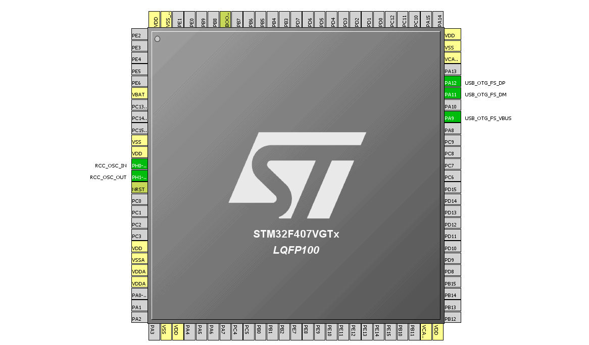
Note that STM32CubeMx marked all “busy” pins:
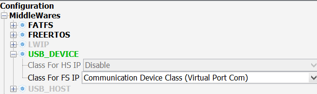
Finally, we should set the VCP mode to our USB device:
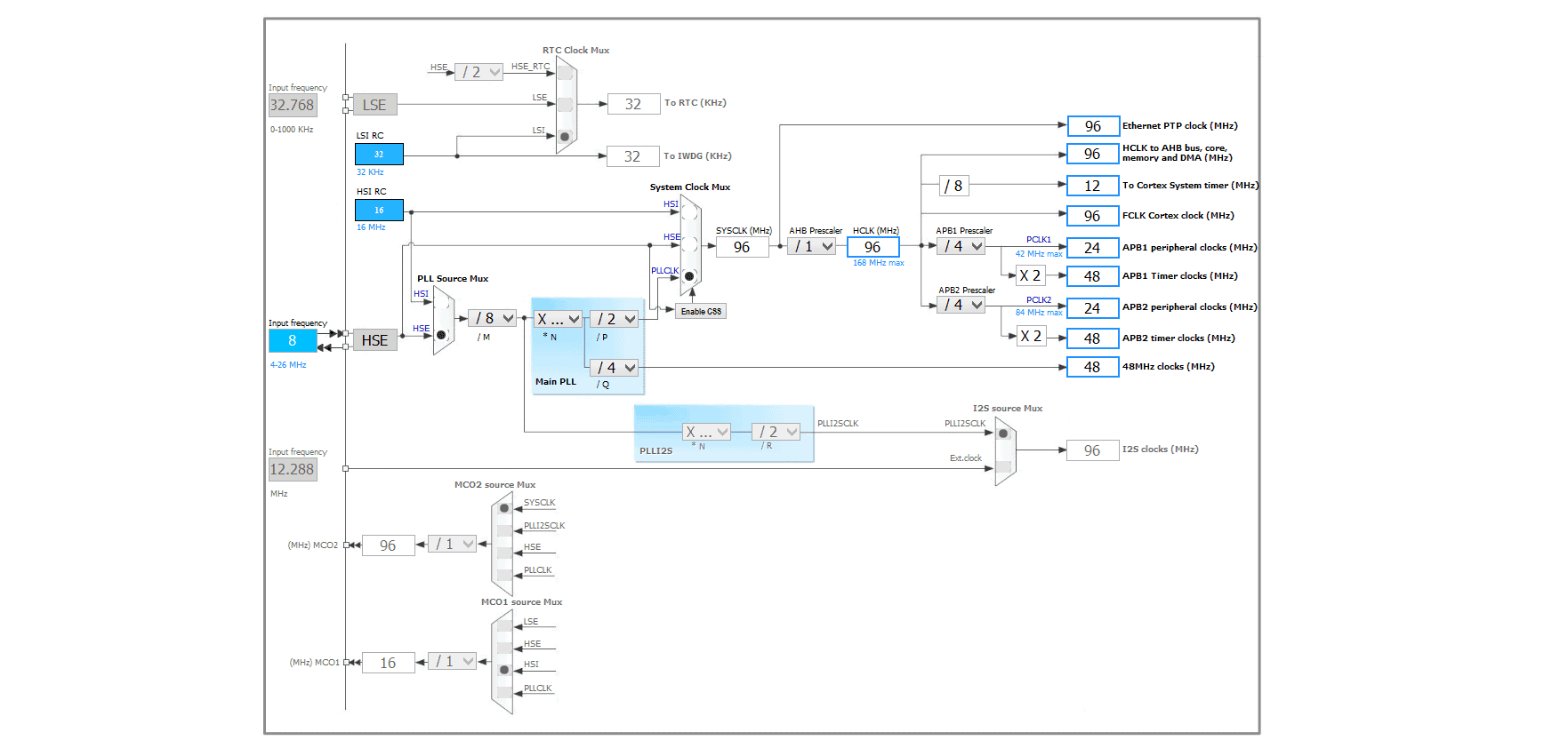
So, the first configuration step is now finished, let’s proceed to the “Clock Configuration” tab. We can setup all of the MCU frequencies there. The final clock settings for this project are shown in the picture:
The next is “Configuration” tab, where we can access the various USB peripheral settings. And, firstly, we should enable the VBus pin (PA9). In order to do this we should click on the USB_FS button:

Secondly, click on the USB_DEVICE button. A new configuration window will be shown, where different USB properties, such as VID and PID, can be set. In this project we have no need to change any of them, so it’s time to generate the new project! In contrast to previous posts let’s compile the project without any changes. After that let’s program the MCU and connect the board to the PC. As a result we’ll see a new device in the Device Manager:

So, the generated project works fine 🙂
As we decided at the beginning of this post, we should send an amount of data from the development board to the PC. All necessary functions for data exchange via USB Virtual COM Port are located in the file usbd_cdc_if.c:
- CDC_Receive_FS() – for receiving data
- CDC_Transmit_FS – for transmitting data
In this project we’ll send eight bytes with the timeout (1 second). For the delay implementation HAL_Delay() function can be used. Delay value in milliseconds should be passed into this function. Thus, let’s add some code in the function main():
int main(void)
{
	/* USER CODE BEGIN 1 */

	/* USER CODE END 1 */

	/* MCU Configuration----------------------------------------------------------*/

	/* Reset of all peripherals, Initializes the Flash interface and the Systick. */
	HAL_Init();

	/* Configure the system clock */
	SystemClock_Config();

	/* Initialize all configured peripherals */
	MX_GPIO_Init();
	MX_USB_DEVICE_Init();

	/* USER CODE BEGIN 2 */

	/* USER CODE END 2 */

	/* USER CODE BEGIN 3 */
	uint8_t testDataToSend[8];

	for (uint8_t i = 0; i < 8; i++)
	{
		testDataToSend[i] = i;
	}

	/* Infinite loop */
	while (1)
	{
		HAL_Delay(1000);
		CDC_Transmit_FS(testDataToSend, 8);
	}
	/* USER CODE END 3 */
}
Let’s compile the edited project and try to connect the board again. In order to receive the data we can use any serial port monitor utility:
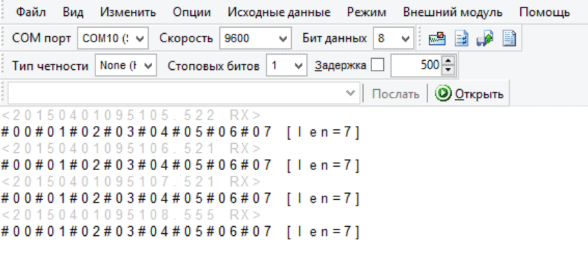
As you see the received data equals the data in our project, it means that the data exchange was successful! So, this article has come to the end, we thank you for your attention and hope you’ll visit our site again! 🙂
Full project - STM32Cube_USB_VCP_Project.


 usage with STM32CubeMx.")

Hi my friend, could you upload the code please?
Yes, of course =) I've added the link at the end of the post.
Thank you!! My friend 🙂
There are a number of STM32F4 Discovery boards supported by the STM32Cube software and you haven’t said which you’re using, but I’ve had exactly the same issue with the Discovery board with the F401VCT MCU. After installing the STM virtual COM port driver, Windows Device Manager showed a STMicroelectronics Virtual COM Port, but with a yellow warning mark. The COM port was not accessible with a terminal appliaction (PUTTY). I eventually found that there is a problem with source code output from the STMCube program. But there is a simple fix:
Open a new STM32Cube project and enable the USB_OTG_FS as Device Only and select CDC Virtual Port Com (sic) from the MiddleWares USB_Device drop-down.
Generate the source code with no other changes needed to any USB settings.
In file usbd_cdc_if.c, change #define USB_HS_MAX_PACKET_SIZE from 512 to 256.
In file usbd_cdc.c, change the #define CDC_DATA_HS_MAX_PACKET_SIZE from 512 to 256.
Hello!
I've used the board with STM32F407VG MCU (like shown at the screenshot).
Yes its correct how you do, but I've used below windows 8.1 and STM32F407VG, and an error is displayed with the device, for this reason I posted the solution for that error. And thank you for your code, it was a gread help.
Thank you for your additions!
Change heap and stack. I put both to 0x2000. And yellow mark will disappear.
But let me advice you to grow the next values in to 64:
/* USER CODE BEGIN PRIVATE_DEFINES */
/* Define size for the receive and transmit buffer over CDC */
/* It's up to user to redefine and/or remove those define */
#define APP_RX_DATA_SIZE 64
#define APP_TX_DATA_SIZE 64
Thank you bro. what you said was a miracle for me after two days searching!!
Dear Sir
Thank you for your very good post. it was really helpful for me.
Everything is OK. My only problem is that, my Os is Win7 and it doesn't install the Virtual Com Port Driver and it has yellow icon in Device Manager. Do you have any idea?
Hello!
Have you tried to install Virtual Com Port Driver from ST official site?
I did and it still doesn't work. I don't even have it under com ports, just "unknown USB device"
First of all you can try to increase stack and heap size as it's written in the comments.
After that, if the Windows Virtual com-port drivers are correct you should change the electrical connection between the board and PC.
Thanks this helped me a lot starting with USB The more difficult part seems to be: CDC_Receive_FS()
any example?
Hello!
CDC_Receive_FS() is being called automatically when the data is received. You can get the data pointer and data length from arguments of this function.
do this function "CDC_Transmit_FS" works in while loop only?
You can call it from another place.
Hmmm
I rebuilt the project and loaded FW into STM32F417ZG (previously I've changed MC from 407Vx to 417ZG). It does not working. I looked inside the sources and I can say my board did not try to connect to Windows host. I'm sorry.
I try to sugar the pill. You done well work! Thank you!
Thank's for an excellent example - I'm using the new STM32CubeIde with the embedded STM32CubeMx - I could configure and compile without errors. However when I try to connect I get a device busy - I'm using an STM32F407ZGT and MAC
Hello!
You should try to increase stack and heap sizes. I hope this can help.
Thank you soooo very berry much! 🙂
I was strugglung long time, to even get a single char sent via USB, but with you help, it worked!
Thank you very much for your comment! 🙂