Let's continue with STM32CubeMx application and different MCU units. Today we'll configure and use the STM32 USART interface!
We'll set ourselves the following task:
- to transmit data via USART2 unit
- and to receive this data with the help of the USART1
Thus, in case of receiving the correct amount of data we can see that the USART module is configured correctly. I'll use the STM32F4Discovery development board so the project should be created for STM32F4 microcontroller. In order to conneсt USART1 and USART2 units we should implement the following schematic:
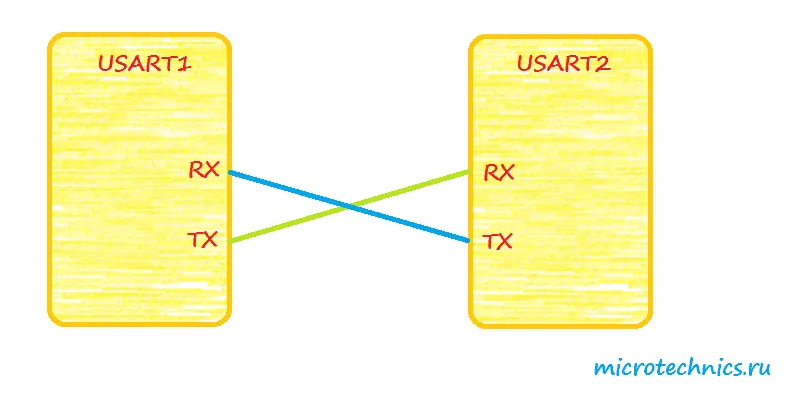
Note that USART1 Rx pin is connected to USART2 Tx pin and vice versa. Here is a table from STM32F407VGT6 datasheet with USART pin descriptions:
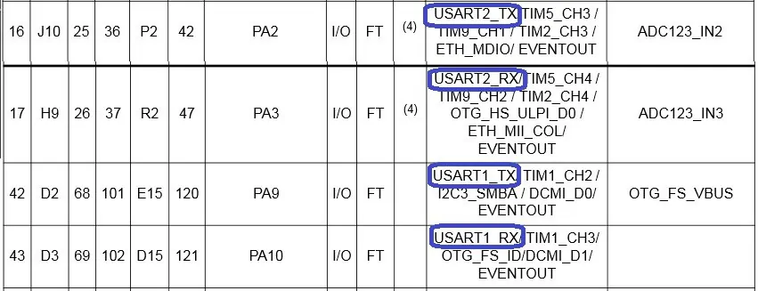
Thus, these pins should be connected in this way:
- PA2 - PA10
- PA3 - PA9
So, the electrical connections are quite clear now. Let's proceed to the STM32CubeMx - we should create the new project end enable all required units:
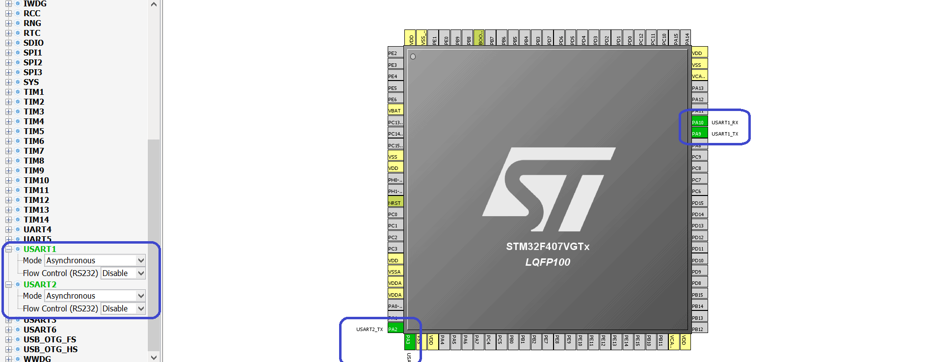
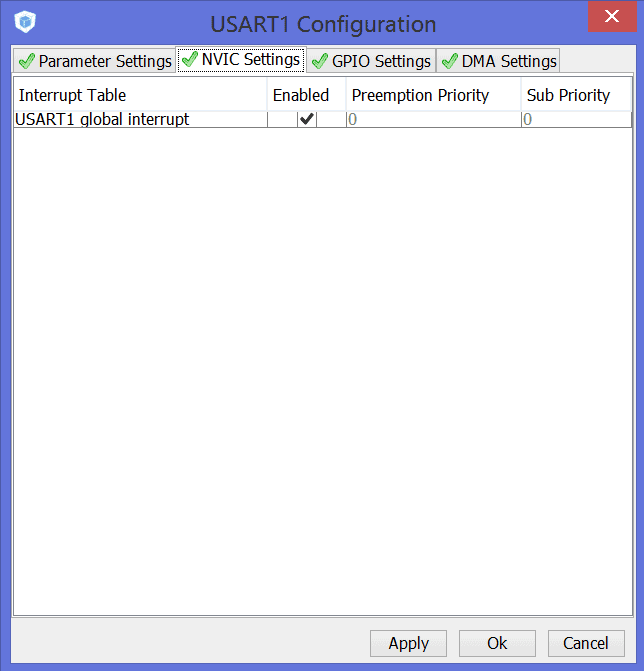
In order to configure some extra parameters, such as baudrate, number of stop-bits, number of data bits and others, we should open the "Configuration" tab. In this project we set baudrate to 9600 b/s. Moreover, the USART1 and USART2 global interrupts should be enabled:
So, we finish with configuration of the MCU and can generate the project. After that we can open it and add some extra code 🙂 As you see STM32CubeMx has already initialized STM32 USART module:
/* Initialize all configured peripherals */
MX_GPIO_Init();
MX_USART1_UART_Init();
MX_USART2_UART_Init();
Moreover, all necessary interrupts have also been included in the stm32f4xx_it.c file:
/**
* @brief This function handles USART2 global interrupt.
*/
void USART2_IRQHandler(void)
{
	/* USER CODE BEGIN USART2_IRQn 0 */

	/* USER CODE END USART2_IRQn 0 */
	HAL_UART_IRQHandler(&huart2);
	/* USER CODE BEGIN USART2_IRQn 1 */

	/* USER CODE END USART2_IRQn 1 */
}


/**
* @brief This function handles USART1 global interrupt.
*/
void USART1_IRQHandler(void)
{
	/* USER CODE BEGIN USART1_IRQn 0 */

	/* USER CODE END USART1_IRQn 0 */
	HAL_UART_IRQHandler(&huart1);
	/* USER CODE BEGIN USART1_IRQn 1 */

	/* USER CODE END USART1_IRQn 1 */
}
HAL library provides some functions for transmitting and receiving data:
HAL_StatusTypeDef HAL_UART_Transmit(UART_HandleTypeDef *huart, uint8_t *pData, uint16_t Size, uint32_t Timeout);
HAL_StatusTypeDef HAL_UART_Receive(UART_HandleTypeDef *huart, uint8_t *pData, uint16_t Size, uint32_t Timeout);
HAL_StatusTypeDef HAL_UART_Transmit_IT(UART_HandleTypeDef *huart, uint8_t *pData, uint16_t Size);
HAL_StatusTypeDef HAL_UART_Receive_IT(UART_HandleTypeDef *huart, uint8_t *pData, uint16_t Size);
HAL_StatusTypeDef HAL_UART_Transmit_DMA(UART_HandleTypeDef *huart, uint8_t *pData, uint16_t Size);
HAL_StatusTypeDef HAL_UART_Receive_DMA(UART_HandleTypeDef *huart, uint8_t *pData, uint16_t Size);
The differences between these functions are quite clear - just look at their names 🙂 For example these two use DMA unit for data exchange:
HAL_StatusTypeDef HAL_UART_Transmit_DMA(UART_HandleTypeDef *huart, uint8_t *pData, uint16_t Size);
HAL_StatusTypeDef HAL_UART_Receive_DMA(UART_HandleTypeDef *huart, uint8_t *pData, uint16_t Size);
I've decided to use interrupt mode, so let's add some code in the main() function:
/* Includes ------------------------------------------------------------------*/
#include "stm32f4xx_hal.h"

/* USER CODE BEGIN Includes */

/* USER CODE END Includes */

/* Private variables ---------------------------------------------------------*/
UART_HandleTypeDef huart1;
UART_HandleTypeDef huart2;

/* USER CODE BEGIN PV */
// Declare the data buffers
uint8_t transmitBuffer[32];
uint8_t receiveBuffer[32];

/* USER CODE END PV */

/* Private function prototypes -----------------------------------------------*/
void SystemClock_Config(void);
static void MX_GPIO_Init(void);
static void MX_USART1_UART_Init(void);
static void MX_USART2_UART_Init(void);

/* USER CODE BEGIN PFP */

/* USER CODE END PFP */

/* USER CODE BEGIN 0 */

/* USER CODE END 0 */

int main(void)
{
	/* USER CODE BEGIN 1 */

	/* USER CODE END 1 */

	/* MCU Configuration----------------------------------------------------------*/

	/* Reset of all peripherals, Initializes the Flash interface and the Systick. */
	HAL_Init();

	/* Configure the system clock */
	SystemClock_Config();

	/* Initialize all configured peripherals */
	MX_GPIO_Init();
	MX_USART1_UART_Init();
	MX_USART2_UART_Init();

	/* USER CODE BEGIN 2 */
	// Set the values of transmit data and clear the receive buffer
	for (unsigned char i = 0; i < 32; i++)
	{
		transmitBuffer[i] = i + 1;
		receiveBuffer[i] = 0;
	}

	// Start receiving the data via USART1
	HAL_UART_Receive_IT(&huart1, receiveBuffer, 32);
	// Transmit data via USART2
	HAL_UART_Transmit_IT(&huart2, transmitBuffer, 32);
	/* USER CODE END 2 */

	/* USER CODE BEGIN 3 */
	/* Infinite loop */
	while (1)
	{
	}
	/* USER CODE END 3 */
}
No we can compile the project and program the microcontroller! After that we can start the debug session and look at the receiveBuffer[] data array:
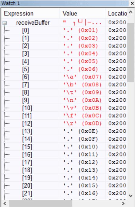
As you see the received data and the transmitted data are the same, thus, our project works perfect! This concludes this article, we will be glad to see you on our site again! 🙂


 usage with STM32CubeMx.")

Hi Aveal,
Does this code work? Or do we need any callback function?
Thanks,
Aks.
Hi!
Yes, it works.